
Jiangsu Huachen Transformer Co.,Ltd.
- All
- Product Name
- Product Keyword
- Product Model
- Product Summary
- Product Description
- Multi Field Search

Views: 0 Author: Site Editor Publish Time: 2026-08-31 Origin: Site


Managing voltage volatility at the grid edge and in specialized industrial applications requires precise regulation. Facility managers and grid engineers must determine if dynamic, under-load voltage regulation can be integrated directly into compact, ground-level enclosures without compromising safety, footprint, or overall operational budgets. Standard distribution equipment is designed for static voltage adjustment. When facing severe voltage sags or swells, operators often ask can pad mount transformers have load tap changers. The short answer is yes, but it requires custom engineering. This guide examines the engineering constraints involved in specifying load tap changers (LTCs) in pad mounted transformers. We outline the framework for deciding between custom on-load solutions versus standard off-load configurations. You will learn how to evaluate space limitations, oil management requirements, and alternative voltage regulation methods for your distribution network.
Feasibility: While standard pad mounted transformers utilize De-Energized Tap Changers (DETC), custom engineering allows for the integration of On-Load Tap Changers (OLTC) in specific, high-requirement applications.
Primary Constraints: Integrating an LTC into a pad mount design significantly alters the physical footprint, requires separate oil compartments to manage arcing degradation, and increases upfront capital expenditure.
Ideal Use Cases: On-load tap changing at the pad level is typically reserved for renewable energy collector systems (solar/wind), highly sensitive industrial loads, and isolated grid-edge voltage regulation.
Maintenance Reality: Specifying an LTC shifts the maintenance profile from a low-touch distribution asset to a high-maintenance piece of equipment requiring regular oil testing and mechanical inspections.
Electrical grids rarely operate in a perfect state. Power travels across long distances, encountering resistance and reactance along the way. This causes a natural voltage drop by the time electricity reaches the end user. Transformers need a mechanism to compensate for this loss. Taps provide this essential function by allowing operators to adjust the output voltage to match specific site requirements.
Tap changers regulate the output voltage of a transformer by altering the number of active turns in one winding. This physical change adjusts the transformer's voltage ratio. If the incoming grid voltage is too low, the tap changer reduces the number of primary turns. This increases the secondary voltage output. Conversely, if the incoming voltage is too high, adding primary turns lowers the secondary output. This mechanical adjustment keeps the delivered power within acceptable equipment tolerance ranges.
The vast majority of distribution networks rely on static voltage regulation. The standard utility-grade configuration utilizes a De-Energized Tap Changer (DETC). You will typically find these 5-position tap changers located in the primary high-voltage cabinet of a standard Pad Mounted Transformer. They provide a simple, reliable way to adjust voltage ratios during initial installation or seasonal load changes.
Safety and operational protocols for DETC units are strict. You must never operate non-excitation taps while the transformer is energized. Doing so will cause catastrophic arcing, equipment failure, and severe injury. Operators must completely de-energize both the primary and secondary sides of the transformer. They must lock out the power sources, test for dead voltage, and apply proper grounds before turning the tap changer handle.
The primary use case for a DETC is compensating for long-term, static voltage drop on distribution feeders. They do not handle dynamic load fluctuations. If a facility experiences sudden voltage sags during heavy motor startups, a DETC cannot react. It remains a static device designed for stable, predictable grid conditions.
Some applications demand real-time voltage regulation. This requires an On-Load Tap Changer (OLTC). These complex mechanisms adjust the tap of the transformer winding while the unit remains under active load. They regulate voltage seamlessly without interrupting power flow to downstream equipment. This capability is standard in large substation transformers but rare at the distribution level.
Bringing this technology to the ground level presents unique engineering challenges. Manufacturers must adapt large-scale On-Load Tap Changer Power Transformer technology for compact spaces. They miniaturize the motor drives, transition resistors, and switching mechanisms to fit inside tamper-proof enclosures. These modified enclosures must still meet strict public safety standards for ground-level equipment. The resulting unit is a highly specialized hybrid, blending substation-level control with distribution-level packaging.
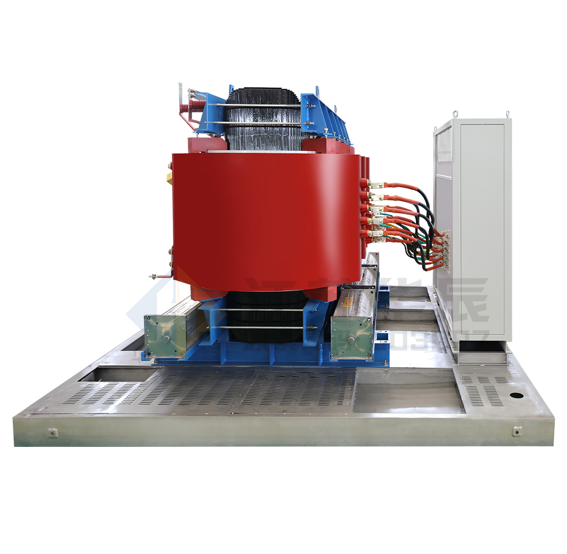
Evaluating the necessity of active voltage regulation requires strict problem framing. Engineers must weigh the operational benefits against physical and financial constraints. Pad mounts do not generally have load tap changers by default. Specifying one means moving away from standardized catalog items into custom engineering territory. Success depends on proving that standard off-load regulation absolutely cannot meet the facility's power quality requirements.
Integrating an LTC mechanism demands significant physical space. The tap changer itself, along with its motor drive and control circuitry, adds considerable bulk. This physical volume must fit within a secure, weather-resistant housing. Engineers must expand the traditional transformer cabinet dimensions to accommodate these moving parts safely, often adding 24 to 36 inches of depth to the unit.
This expansion impacts the tamper-proof, low-profile design mandated by standard specifications like ANSI/IEEE C57.12.34. Pad mounted transformers sit in public spaces, parking lots, and commercial yards. They must resist vandalism and environmental ingress. Enlarging the enclosure to house an LTC makes it harder to maintain these strict security and aesthetic standards. The custom enclosure requires heavier gauge steel, reinforced hinges, and specialized locking mechanisms to support the added weight and dimensions.
Switching electrical contacts under load creates an unavoidable physical reaction: arcing. When the LTC moves from one tap to another, the momentary break in the circuit generates a high-energy arc. This arc degrades the surrounding insulating fluid. It creates carbon deposits and combustible gases like acetylene and ethylene. Over time, this carbonization severely reduces the dielectric strength of the oil.
To prevent catastrophic failure, engineers must isolate this arcing process. They cannot allow contaminated oil to mix with the main transformer tank. Custom LTC pad mounts require a separate, sealed oil compartment specifically for the tap changer. Alternatively, manufacturers may utilize vacuum-type tap changers. Vacuum interrupters extinguish the arc inside a sealed vacuum bottle. This prevents oil contamination entirely, though it adds significant mechanical complexity to the design.
Custom engineering drives up capital expenditure. A pad mount equipped with an LTC costs substantially more than a standard DETC unit. The specialized enclosure, motor drives, control relays, and separate oil compartments all contribute to a higher upfront investment. Procurement teams must justify this premium through rigorous financial analysis.
Evaluating the return on investment requires looking at avoided losses. Calculate the cost of facility downtime caused by voltage sags. Quantify the potential damage to sensitive downstream equipment from sustained voltage swells. If the financial risk of unstable voltage exceeds the premium of the custom transformer, the investment makes sense. Otherwise, standard distribution equipment remains the most prudent choice.
Renewable energy generation introduces extreme volatility to the distribution grid. Solar arrays and wind turbines produce power intermittently based on environmental conditions. Cloud cover or sudden wind gusts cause rapid fluctuations in power output. This intermittent generation creates dynamic voltage swings throughout the collector system.
Pad-level LTCs help manage this volatility directly at the source. They maintain grid compliance by smoothing out voltage profiles before the power reaches the main substation. This localized regulation optimizes power export at the inverter or turbine level. It prevents over-voltage tripping, ensuring the renewable asset remains online and productive during fluctuating weather conditions.
Certain industrial processes cannot tolerate standard utility voltage bandwidths. Precision manufacturing, semiconductor fabrication, and heavy robotics require tightly controlled power. Even minor voltage sags can disrupt automated assembly lines, causing massive material waste and production delays. Standard DETC transformers cannot react fast enough to protect these processes.
Data centers face similar vulnerabilities. While they utilize massive Uninterruptible Power Supply (UPS) systems, relying on batteries for minor voltage fluctuations degrades battery lifespan. An LTC-equipped pad mount acts as a primary defense against voltage instability. It regulates the incoming feed before the UPS systems need to engage. This preserves battery health and provides a more stable baseline voltage for the entire facility.
Rural and sprawling suburban distribution networks often feature exceptionally long feeder lines. As power travels miles away from the primary substation, voltage levels drop significantly. Homes and businesses at the very end of these lines frequently experience chronic low voltage during peak demand hours.
Utilities sometimes deploy pad mounts with LTCs at these critical grid-edge locations. These active units boost the voltage locally, ensuring the utility maintains ANSI C84.1 voltage limits for end-users. This localized approach prevents the need to upgrade miles of heavy transmission cable. It provides a targeted, equipment-based solution to a geographic infrastructure problem.
If a custom LTC pad mount proves unfeasible due to space or budget constraints, engineers must evaluate alternatives. Managing voltage levels in the distribution network does not always require a hybrid transformer. Several standard approaches offer active regulation using traditional equipment configurations. Each alternative presents distinct trade-offs between footprint, control, and capital expenditure.
The most common alternative relies on centralized control. Utilities use the primary substation transformer to regulate voltage for the entire feeder line. This large-scale equipment already features robust, heavy-duty LTC mechanisms designed for continuous operation.
The primary trade-off involves localized control versus centralized regulation. Substation LTCs adjust the voltage for everyone on the line simultaneously. They cannot fix a localized voltage drop issue occurring exclusively at one specific industrial park at the end of the feeder. Relying on upstream regulation works well for general grid stability but fails to address isolated, site-specific power quality problems.
When localized control is necessary, engineers often install separate Step Voltage Regulators (SVRs). You place these pad-mounted regulators directly alongside standard DETC transformers. The SVR handles the dynamic voltage adjustments, while the standard transformer handles the step-down function.
This multi-unit approach increases the overall installation footprint. You must pour multiple concrete pads and route complex cabling between the units. It also increases multi-unit installation costs. However, it allows procurement teams to purchase standardized, off-the-shelf equipment. This avoids the long lead times and custom engineering premiums associated with hybrid LTC pad mounts.
Modern renewable energy sites leverage software-driven solutions. Smart inverters utilize solid-state technology to provide reactive power (VAR) support. By injecting or absorbing reactive power, these inverters actively control the voltage level at the point of common coupling.
The trade-off centers on software limits versus physical tap adjustments. Smart inverters offer incredibly fast response times without moving mechanical parts. However, their ability to regulate voltage is limited by their maximum current rating and the physical characteristics of the grid. They cannot provide the massive, brute-force voltage correction that a physical tap changer delivers during severe grid disturbances.
Comparison of Voltage Regulation Alternatives
Regulation Method | Primary Advantage | Primary Disadvantage | Best Application Scenario |
|---|---|---|---|
Custom LTC Pad Mount | All-in-one localized dynamic control | High capital expenditure, custom footprint | Space-constrained critical industrial sites |
Upstream Substation LTC | Zero localized footprint or capital cost | Cannot fix isolated grid-edge issues | General residential/commercial distribution |
Step Voltage Regulators (SVR) | Uses standard off-the-shelf equipment | Requires multiple concrete pads | Rural feeders with ample ground space |
Smart Inverters | Instantaneous solid-state response | Limited correction capacity | Solar arrays and wind collector systems |
Specifying an LTC shifts the maintenance profile of your equipment. A standard pad mount is a low-touch asset. An LTC-equipped unit is a high-maintenance machine. The primary risk involves mechanical wear of the moving contacts and rapid oil degradation from continuous arcing. This drives up operational expenditure over the equipment's lifespan.
Mitigation requires careful specification during the procurement phase. Engineers should specify vacuum-type LTCs whenever possible. Vacuum interrupters eliminate oil carbonization because the arc never touches the insulating fluid. This drastically extends maintenance intervals. It reduces the need for frequent oil testing, filtering, and contact replacement, ultimately lowering long-term operational costs.
Maintenance Task Comparison
Maintenance Task | Standard DETC Transformer | Custom OLTC Transformer (Oil-Type) |
|---|---|---|
Visual Inspection | Annual | Quarterly |
Dissolved Gas Analysis (DGA) | Every 3-5 Years | Annually (Main Tank & LTC Compartment) |
Contact Wear Inspection | Never (Sealed Unit) | Every 50,000 Operations |
Oil Filtration/Replacement | Rarely Required | Every 3-5 Years (LTC Compartment) |
Motor Drive Lubrication | Not Applicable | Annually |
Custom engineering significantly extends manufacturing lead times. You can often procure standard off-the-shelf pad mounts within a few months. A custom-designed unit with an integrated LTC may take over a year to engineer, build, and test. This delay can derail tight construction schedules for new facilities or renewable energy projects.
Mitigation relies on proactive project management. Engage with transformer manufacturers as early as possible in the design phase. Do not wait until civil work begins to order custom electrical equipment. Furthermore, if managing a large fleet or multiple sites, standardize your custom specifications. Ordering identical custom units across multiple projects streamlines the manufacturer's engineering process and reduces overall lead times.
The larger footprint and increased weight of an LTC-equipped unit create civil engineering challenges. These oversized transformers will not fit on standard pre-cast concrete pads. Placing a heavy, unbalanced custom unit on an inadequate foundation leads to structural cracking, uneven settling, and potential oil leaks.
Mitigation requires custom civil engineering designs. Structural engineers must execute specific steps to ensure a safe installation:
Obtain certified vendor drawings showing the exact center of gravity for the custom unit.
Calculate soil bearing capacity to support the increased equipment weight.
Design a custom rebar grid to prevent pad cracking under uneven loads.
Map the primary and secondary conduit windows to match the expanded cabinet footprint.
Pour the concrete and allow a full 28-day cure before rigging the transformer into place.
Audit your facility's power quality logs to identify the exact frequency and duration of voltage sags before specifying custom equipment.
Calculate the overall lifecycle expenditure of maintaining a custom LTC unit versus installing a standard transformer alongside a separate step voltage regulator.
Specify vacuum-type tap changers in your procurement documents to eliminate oil carbonization risks and reduce maintenance frequency.
Consult directly with a specialized transformer manufacturer to request custom enclosure modeling and precise weight calculations.
Redesign your civil concrete pad layouts and conduit windows to accommodate the expanded footprint of the custom enclosure.
A: An NLTC requires the transformer to be completely de-energized and grounded before adjusting the voltage taps. An OLTC actively adjusts the voltage taps while the transformer remains energized and under load. This provides dynamic, real-time voltage regulation without interrupting power flow to downstream facility equipment.
A: The voltage output is directly proportional to the number of active turns in the transformer windings. Decreasing the number of active primary turns increases the secondary voltage output. Increasing the primary turns lowers the secondary voltage, allowing operators to compensate for grid voltage fluctuations.
A: On a standard utility-grade pad mounted transformer, the de-energized tap changer is typically located inside the primary high-voltage cabinet. It is usually positioned above the primary bushings and features a rotary handle for manual adjustment by qualified personnel.
A: You must completely de-energize both the primary and secondary sides of the transformer. Apply proper lockout/tagout procedures, verify the absence of voltage, and ground the equipment. Only after ensuring a zero energy state should you manually turn the tap changer handle to the desired position.
A: No. Operating a standard de-energized tap changer while the transformer is energized will cause catastrophic arcing. This leads to immediate equipment failure, explosive oil ignition, and severe or fatal injury to the operator. Always de-energize the unit before operation.
A: An integrated on-load tap changer significantly increases the footprint. It requires an expanded cabinet to house the motor drive, control circuitry, and a separate oil compartment. This can increase the overall width and depth of the transformer by 20% to 40% compared to standard units.


