
Jiangsu Huachen Transformer Co.,Ltd.
- All
- Product Name
- Product Keyword
- Product Model
- Product Summary
- Product Description
- Multi Field Search

Views: 0 Author: Site Editor Publish Time: 2026-08-26 Origin: Site


Determining exactly how many houses can a pad mounted transformer serve dictates the reliability of any residential development. Sizing distribution infrastructure requires a precise balance. Over-sizing wastes capital expenditure and increases continuous no-load losses on the utility grid. Under-sizing risks equipment failure, thermal degradation, and widespread utility outages during peak demand. You cannot rely on generic rules of thumb for modern residential distribution. Today's homes feature entirely different electrical profiles driven by Level 2 electric vehicle (EV) chargers, electric heat pumps, and induction ranges. Relying on legacy estimates guarantees premature equipment overloading. To build resilient power networks, developers and utility engineers must adopt a systematic approach. By calculating load requirements, applying utility diversity factors, and selecting the correct equipment specifications, you can determine the exact capacity needed to support modern residential loads reliably.
Capacity Variance: A standard 25 kVA pad mounted transformer can serve anywhere from 3 to 10 homes, heavily dependent on square footage, HVAC type (gas vs. electric), and regional climate.
Load Diversity is Critical: Utility engineers rely on coincidence factors—recognizing that not all houses draw peak load simultaneously—to safely maximize the number of homes per unit.
Equipment Selection: Single-phase, oil-immersed distribution transformers remain the industry standard for residential subdivisions due to their cost-efficiency, thermal management, and tamper-proof safety designs.
Future-Proofing: Modern load calculations must account for the rapid adoption of Level 2 EV charging, electrification trends, and auxiliary neighborhood loads to prevent premature transformer overloading.
Transformer capacity is a function of the unit's kVA rating divided by the diversified peak demand per connected home. You cannot simply add up the main breaker sizes of every house on the street. A house with a 200-amp service panel does not draw 200 amps continuously. If it did, that single home would require a 48 kVA transformer all to itself. Instead, engineers calculate the maximum expected simultaneous draw across a group of homes to size the equipment appropriately.
Utility deployments utilize standardized kVA ratings for residential neighborhoods. The most common sizes include 25 kVA, 37.5 kVA, 50 kVA, 75 kVA, 100 kVA, and occasionally 167 kVA for high-density applications. The actual number of homes each unit supports varies drastically based on the energy profile of the subdivision.
A standard 25 kVA unit serves as an excellent baseline. In a neighborhood featuring large, all-electric homes with heat pumps and EV chargers, a 25 kVA unit might only safely support 3 houses. However, in a development where homes utilize natural gas for primary heating, water heating, and cooking, that same 25 kVA unit can easily serve up to 10 smaller homes. The thermal load on the transformer remains manageable because the heavy heating loads are shifted to the gas utility infrastructure.
Stepping up the capacity changes the distribution topology. A 50 kVA unit typically handles 8 to 15 homes, depending on those same variables. A 100 kVA unit can often support 15 to 30 homes. Using larger transformers allows utilities to maximize coincidence factors, but it requires longer secondary service cables, which introduces severe voltage drop concerns.
Estimated Residential Capacity by Transformer Size
Transformer Rating (kVA) | All-Electric Homes (High Demand) | Mixed-Fuel Homes (Gas/Electric) | Typical Application |
|---|---|---|---|
25 kVA | 3 - 4 homes | 6 - 10 homes | Cul-de-sacs, rural residential |
37.5 kVA | 4 - 6 homes | 10 - 14 homes | Small suburban streets |
50 kVA | 8 - 10 homes | 12 - 15 homes | Standard subdivision blocks |
75 kVA | 10 - 14 homes | 15 - 22 homes | Medium density developments |
100 kVA | 15 - 20 homes | 20 - 30 homes | High density, townhomes |
For decades, utility averages allocated roughly 4 to 7 kVA per house. This historical rule of thumb worked perfectly for homes built in the 1990s with standard lighting and appliance loads. Today, modern National Electrical Code (NEC) Article 220 load calculation requirements demand a more rigorous approach. Article 220 provides specific demand factors for general lighting, small appliance branch circuits, and heavy motor loads.
For example, the NEC requires calculating general lighting load at 3 volt-amperes (VA) per square foot. It also mandates adding 1,500 VA for each 20-ampere small-appliance branch circuit. Relying on a flat 5 kVA per house estimate in a new development featuring electric vehicle infrastructure will result in overloaded transformers, tripped primary fuses, and degraded insulation. Field engineers must run the actual math based on the architectural electrical plans before specifying the transformer size.
To accurately determine capacity limits, engineers must evaluate the specific electrical characteristics of the housing development. Several critical variables directly impact the thermal loading of the distribution equipment.
The choice of primary heating fuel creates the most dramatic difference in residential demand. Homes utilizing natural gas for furnaces and water heaters exert minimal winter strain on the electrical grid. The electrical draw is limited to blower motors and control boards, usually pulling less than 10 amps.
In contrast, all-electric homes utilizing resistive heat or large heat pumps draw massive amounts of current during winter peaks. A single 15 kW electric furnace strip heater draws over 62 amps at 240 volts. If multiple homes on the same transformer activate their emergency heat strips simultaneously during a cold snap, the transformer will experience severe thermal overload. This single variable often cuts the number of homes a transformer can serve in half.
Base electrical load scales proportionally with square footage. Larger homes require more general lighting circuits, more receptacle outlets, and larger air conditioning tonnage. Beyond the base load, high-draw appliances significantly alter the capacity equation. Electric ranges, double wall ovens, electric clothes dryers, and residential pool pumps introduce substantial intermittent spikes. While these appliances rarely run 24/7, their combined peak demand during evening hours consumes available kVA capacity rapidly.
Typical Residential Appliance Load Profiles
Appliance / System | Typical Power Draw (kW) | Operating Characteristic |
|---|---|---|
Electric Furnace (Resistive) | 10.0 - 20.0 kW | Continuous during cold snaps |
Level 2 EV Charger | 7.2 - 11.5 kW | Continuous (6-8 hours) |
Electric Range / Oven | 5.0 - 12.0 kW | Intermittent (Evening peak) |
Central Air Conditioner | 3.0 - 5.0 kW | Cyclic (Summer peak) |
Electric Clothes Dryer | 4.0 - 6.0 kW | Intermittent |
Natural Gas Furnace (Blower) | 0.5 - 1.0 kW | Cyclic |
Electric vehicle charging fundamentally changes residential load profiles. Traditional appliances cycle on and off, allowing the transformer oil to cool. A Level 2 EV charger operates as a continuous load. Drawing anywhere from 32 to 48 amps continuously for 6 to 8 hours prevents the transformer from shedding heat during the overnight off-peak hours.
When calculating how many homes a unit can support, engineers must assume a high probability of simultaneous EV charging. If four homes on a 25 kVA transformer plug in their EVs at 6:00 PM, the continuous draw alone can consume over 60% of the transformer's total nameplate rating. This leaves very little headroom for HVAC and cooking loads, forcing utilities to upgrade the transformer to a 50 kVA unit.
Residential transformers rarely serve just the houses. Planners must account for shared infrastructure that draws from the same secondary network. Streetlights, traffic signals at neighborhood entrances, illuminated community signs, and shared irrigation pumps for landscaping all consume available kVA. While a few LED streetlights draw minimal power, a 5 HP community irrigation pump introduces significant inrush current and continuous load that must be factored into the overall capacity limits.
Utility distribution engineering relies heavily on the concepts of diversity and coincidence factors. The diversity factor recognizes that the probability of simultaneous peak demand decreases as the number of connected houses increases.
If you have one house, the coincidence factor is 100%—the transformer must handle that home's absolute peak. If you connect 10 houses, it is statistically impossible for all 10 homes to run their AC, electric ovens, dryers, and EV chargers at the exact same millisecond. The coincidence factor drops to roughly 60% or 70%. This statistical reality allows engineers to size transformers below the sum of the individual peak loads. Maximizing this diversity is the primary reason utilities prefer grouping multiple homes onto a single, properly sized Pad Mounted Transformer rather than giving every home its own small unit.
Steps to Calculate Diversified Residential Load:
Calculate the total connected load for a single home using NEC Article 220 guidelines.
Apply the standard demand factors for appliances and lighting to find the individual peak demand.
Multiply the individual peak demand by the number of homes planned for the transformer.
Apply the utility's specific coincidence factor based on the number of connected homes.
Add any continuous auxiliary loads (e.g., streetlights, lift stations) at 125% of their rating.
Select the next standard transformer kVA size that exceeds the final calculated load.
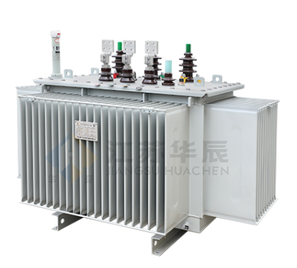
Choosing the correct equipment involves more than just selecting a kVA rating. The physical and operational characteristics of the transformer dictate its lifespan, safety, and performance in residential environments.
Single-phase pad mounted transformers serve as the absolute standard for residential neighborhoods. They step down the utility's medium voltage distribution line to the standard 120/240V split-phase power required by residential service panels. They are compact, cost-effective, and perfectly suited for standalone commercial buildings, small apartment complexes, and standard subdivisions.
Three-phase units are deployed only when specific load requirements demand them. You will find three-phase transformers in large apartment complexes with commercial HVAC systems, high-density residential towers, data centers, or neighborhoods that feature shared commercial-grade pump stations for municipal water or sewage. For standard single-family homes, three-phase power is unnecessary and prohibitively expensive to route.
For outdoor residential use, the Oil-Immersed Distribution Transformer is universally preferred over dry-type alternatives. These units utilize oil natural air natural (ONAN) cooling. The mineral oil inside the tank serves a dual purpose: it acts as a highly effective dielectric insulator and a superior thermal conductor.
The physics of ONAN cooling are highly efficient. As the copper or aluminum windings generate heat under load, the surrounding oil warms and rises to the top of the tank via natural convection. The hot oil then circulates through the external cooling fins (radiators), sheds its heat to the outside air, and sinks back to the bottom of the tank.
This thermal mass allows the transformer to handle short-duration overloads well beyond its nameplate rating without degrading the internal paper insulation. Furthermore, the sealed steel tanks provide unmatched weather resistance against rain, snow, and UV exposure, ensuring decades of reliable outdoor service.
Because these transformers sit at ground level in residential yards, safety is paramount. Modern units utilize "dead-front" construction. In a dead-front design, all high-voltage primary connections are fully insulated and shielded using loadbreak elbows and bushing wells. When a utility worker opens the primary cabinet, there are no exposed live wires or bare terminals.
This design protects the public from accidental electrocution. The enclosures are constructed from heavy-gauge steel, feature tamper-proof locking mechanisms, and are grounded extensively. This robust construction allows them to be safely deployed in areas accessible to children, pets, and landscaping equipment.
The internal wiring configuration of the transformer impacts neighborhood reliability. A radial feed transformer accepts a single primary line from the utility. If that line faults, the transformer and all connected homes lose power until the cable is physically replaced.
A loop feed transformer features two sets of primary bushings (H1A/H1B, H2A/H2B). This allows the primary medium-voltage cable to enter the transformer and loop back out to feed the next transformer down the street.
Advantages of Loop Feed Configurations:
Superior fault isolation during underground cable failures.
Allows utility crews to feed the subdivision from two different directions.
Reduces outage times for residents during maintenance operations.
Utilizes loadbreak elbows to safely disconnect specific transformers without dropping the entire neighborhood.
Procuring the right distribution equipment requires adhering to strict utility frameworks and understanding the engineering trade-offs of different network topologies.
Every deployment must adhere to local utility standards and national guidelines, such as IEEE C57.12.00. These standards dictate specific kVA increments, acceptable impedance values, and loss evaluations. Utilities evaluate transformers based on No-Load (core) losses and Load (winding) losses. Selecting a unit that meets stringent efficiency standards ensures that the grid operates efficiently even when the residential load is minimal during the middle of the night.
Engineers utilize ANSI/IEEE loading guides to determine how far a transformer can be pushed. A 50 kVA unit does not instantly fail if the load hits 51 kVA. Ambient temperature plays a massive role. During winter months, the cold outside air provides superior cooling, allowing the transformer to safely handle loads 20% to 30% above its nameplate rating. Conversely, during a 100-degree summer heatwave, that same unit may struggle to shed heat, reducing its effective overload capacity. Sizing calculations must account for the region's seasonal temperature extremes.
Developers face a constant trade-off between centralized and distributed topologies. Using fewer, larger transformers reduces the total number of transformers purchased and minimizes the amount of medium-voltage primary trenching required. However, it requires massive secondary copper or aluminum cabling to route power from the single transformer to 20 different houses.
A distributed approach uses more, smaller transformers serving fewer homes each. This increases equipment procurement costs but drastically reduces the length and gauge of the secondary service cables. The distributed model often provides better voltage stability and isolates outages to fewer homes during an equipment failure.
Centralized vs. Distributed Transformer Topologies
Topology Type | Transformer Size | Homes Served per Unit | Secondary Cable Length | Voltage Drop Risk |
|---|---|---|---|---|
Centralized | 75 kVA - 100 kVA | 15 - 30 homes | Long (200+ feet) | High |
Distributed | 25 kVA - 50 kVA | 4 - 10 homes | Short (Under 150 feet) | Low |
Executing a residential power distribution plan involves navigating physical, electrical, and logistical risks. Proper mitigation strategies prevent costly rework and ensure long-term grid stability.
The most significant risk of pushing a single large transformer to serve too many houses is secondary voltage drop. As electrical current travels through the secondary service cables to the home, resistance causes the voltage to drop. If a house is located 400 feet away from the transformer, the voltage reaching the main panel may drop below acceptable utility tolerances (typically 114V to 126V).
Severe voltage drop causes flickering lights, inefficient appliance operation, and premature failure of HVAC compressor motors. To mitigate this, engineers must carefully calculate the voltage drop using the conductor's resistance, the expected current, and the distance.
Voltage Drop Mitigation Strategies:
Limit secondary service run lengths to an absolute maximum of 250 feet.
Increase the wire gauge for longer runs (e.g., upgrading from 4/0 aluminum to 350 MCM aluminum).
Position the transformer centrally among the cluster of homes it serves to equalize cable lengths.
Transition to a distributed topology with smaller transformers if voltage drop exceeds 5%.
Physical footprint requirements dictate where equipment can be legally installed. National Fire Protection Association (NFPA) codes and local utility regulations mandate strict fire safety clearances. A mineral oil-filled transformer cannot be placed flush against a combustible structure.
Standard regulations require 10 to 14 feet of clearance from combustible walls, windows, doors, and fire escapes. In high-density housing developments or zero-lot-line townhomes, finding a compliant location for a large pad mounted unit is incredibly difficult. Planners must integrate these clearance zones into the architectural site plans long before concrete is poured.
The procurement reality for distribution transformers is volatile. Lead times for custom configurations can stretch for months. To mitigate project delays, developers should standardize their kVA sizes to align with manufacturer availability and local utility stock. Designing a neighborhood around readily available 50 kVA and 75 kVA units ensures that replacement equipment can be sourced quickly in the event of a failure, preventing extended outages for residents.
To ensure your residential distribution network is properly sized and deployed, execute the following steps:
Consult local utility planners to obtain specific coincidence factors and approved equipment lists for your region.
Conduct a localized NEC Article 220 load calculation that explicitly accounts for primary heating fuels and projected EV adoption rates.
Engage transformer manufacturers during the initial site design phase to secure specification sheets and verify physical clearance requirements.
Standardize your procurement around readily available 50 kVA and 75 kVA units to mitigate supply chain delays.
A: A 50-home subdivision requires multiple transformers distributed throughout the neighborhood to minimize secondary voltage drop. You cannot serve this many homes from a single unit. A standard configuration deploys three to five 50 kVA or 75 kVA units. The exact quantity depends on the homes' square footage, primary heating fuel, and EV charging requirements.
A: Yes, a 25 kVA transformer is designed to run multiple houses. It commonly serves anywhere from 3 to 10 homes. If the homes are all-electric with high winter heating demands, the unit will support closer to 3 homes. If the homes utilize natural gas for heating and cooking, the transformer can easily support up to 10 homes.
A: All-electric homes utilize resistive heat strips or large heat pumps that create massive peak electrical demands during winter. This continuous current draw drastically reduces the number of homes a single transformer can support. Engineers must specify larger kVA units or place fewer homes on each transformer to prevent thermal overload and insulation degradation.
A: Yes, they are highly safe. Modern residential units utilize a dead-front safety design. They are housed in heavily grounded, tamper-resistant steel enclosures. When the cabinet is locked, there are no exposed live wires. This robust construction protects residents, children, and pets from accidental contact with high voltage components.
A: A properly sized oil-immersed distribution transformer typically lasts 25 to 30 years in the field. However, frequent overloading beyond its thermal limits will rapidly degrade the internal paper insulation. Once the insulation breaks down, the unit will experience premature failure, significantly shortening its operational lifespan.
A: Placement is strictly regulated by utility and fire codes. Installations typically require 10 to 14 feet of clearance from combustible walls, windows, doors, and ventilation intakes. These clearances mitigate fire risks associated with the mineral oil inside the tank and ensure utility crews have safe working access.
A: Single-phase transformers step down voltage for standard 120/240V residential applications and serve as the standard for single-family subdivisions. Three-phase transformers provide power for heavy commercial loads, large apartment complexes, or industrial equipment. They are rarely used for standard residential streets due to higher costs and unnecessary capacity.


