
Jiangsu Huachen Transformer Co.,Ltd.
- All
- Product Name
- Product Keyword
- Product Model
- Product Summary
- Product Description
- Multi Field Search

Views: 0 Author: Site Editor Publish Time: 2026-08-06 Origin: Site


Modern infrastructure planning heavily favors underground electric power distribution lines. This approach enhances grid resilience against severe weather, protects equipment from falling debris, and improves site aesthetics for commercial and residential developments. Facility managers, electrical engineers, and site developers face a specific challenge. They must safely step down high-voltage utility power to usable secondary voltages in environments where overhead lines are impractical. This requires secure, ground-level electrical infrastructure.
When planning these electrical systems, understanding how does a pad mounted transformer work ensures safe and reliable power delivery. Knowing the internal mechanics, safety configurations, and operational constraints of these units dictates accurate specification, strict code compliance, and long-term site reliability. A poorly specified unit leads to power bottlenecks, safety hazards, and replacement delays.
Operational Principle: Pad mounted transformers operate on electromagnetic induction, safely stepping down primary utility voltages (e.g., 8,000V - 34,500V) to secondary facility voltages (e.g., 120/240V, 480V) within a secure, grounded enclosure.
System Topology: Selection depends heavily on grid design, requiring buyers to choose between radial feed (single power source) and loop feed (dual power source for redundancy) configurations, as well as single-phase versus three-phase designs.
Safety & Maintenance: Dead-front construction and tamper-resistant enclosures are the modern standards for safety, shielding operators and the public from exposed live parts.
Implementation Realities: Successful deployment requires strict adherence to NEC/NESC clearance zones, precise concrete pad construction, and rigorous grounding and bonding protocols.
Utility companies transmit electricity at high voltages to minimize energy loss over long distances. Buildings and industrial facilities cannot use this high-voltage power directly. Voltage conversion must happen at the service drop before power enters a building's main electrical panel. The ground-level transformer serves as this conversion point.
The physical process relies entirely on electromagnetic induction. Alternating current from the utility grid enters the primary winding of the unit. This current creates a rapidly fluctuating magnetic field within the internal steel core. The magnetic field travels through the core and intersects with the secondary winding. This intersection induces a new, lower voltage in the secondary coils.
The exact step-down voltage depends on the turns ratio. This ratio compares the number of wire wraps on the primary coil to the number of wraps on the secondary coil. If the primary coil has 100 turns and the secondary coil has 10 turns, the voltage drops by a factor of 10. Engineers specify this ratio to match incoming grid voltage with the specific load requirements of the facility.
Common Voltage Conversion Profiles
Application Type | Typical Primary Voltage (Utility) | Typical Secondary Voltage (Facility) |
|---|---|---|
Residential Subdivision | 12,470V or 13,200V | 120/240V (Single-Phase) |
Light Commercial / Retail | 12,470V or 24,940V | 208Y/120V (Three-Phase) |
Heavy Industrial / Manufacturing | 13,800V or 34,500V | 480Y/277V (Three-Phase) |
Safety dictates the physical layout of the cabinet. The enclosure features a strict physical separation between the high-voltage and low-voltage sections. When facing the cabinet doors, the left side typically houses the primary high-voltage incoming utility lines. The right side contains the secondary low-voltage outgoing facility lines.
Rigid steel barrier systems separate these two compartments. When a technician opens the cabinet to work on the secondary side, these barriers protect them from accidental exposure to the primary voltage. The design ensures that routine maintenance, such as checking secondary spade connections or reading meters, happens without exposing personnel to lethal utility-level power.
Understanding the internal hardware helps you evaluate performance, lifespan, and maintenance requirements. Each component plays a specific role in managing electrical loads and thermal stress.
The core and coil assembly acts as the engine of the unit. Manufacturers build the core using specialized magnetic materials. Grain-oriented electrical steel (GOES) is the traditional choice, offering excellent magnetic permeability. Amorphous metal cores provide a high-efficiency alternative. They significantly reduce no-load losses, which is the energy wasted just keeping the unit energized 24/7.
Windings consist of either copper or aluminum. Copper offers superior electrical conductivity and allows for a more compact coil design. It withstands short-circuit mechanical stresses exceptionally well. Aluminum windings weigh less and reduce the initial capital expenditure. Many modern units use aluminum for the primary winding and copper for the secondary winding to balance performance and material expenses.
Transformers generate substantial heat during voltage conversion. They rely on dielectric fluid to manage this thermal load. The fluid serves a dual role. It provides electrical insulation between the internal live parts and dissipates heat away from the core and coils to the outer tank walls.
You must evaluate your fluid options based on site conditions. Traditional highly refined mineral oil remains common due to its proven performance. However, less-flammable natural ester fluids are becoming the industry standard. Natural esters have a much higher fire point. This characteristic reduces required fire safety clearances, allowing installation closer to buildings. They also biodegrade rapidly, simplifying environmental compliance if a leak occurs.
Internal protection mechanisms isolate faults before they damage the grid or the facility. Bayonet fuses provide primary overcurrent protection. Technicians can draw these fuses out externally using a hot stick. Current-limiting fuses sit in series with the bayonet fuses. They operate rapidly to clear high-energy internal faults, preventing catastrophic enclosure failure.
The tap changer allows for manual voltage adjustments. Utility supply voltages fluctuate based on grid demand and distance from the substation. If the incoming voltage drops too low, a technician can adjust the tap changer to alter the turns ratio slightly. This adjustment restores the secondary output to the correct voltage. You must only operate the tap changer when the unit is completely de-energized and grounded.
Routine maintenance requires accurate internal data. Standard accessories provide this visibility without requiring you to open the main tank. Essential monitoring gauges include liquid level indicators, dial-type thermometers, and pressure/vacuum gauges. These tools help technicians identify slow leaks, overheating, or abnormal internal pressure.
The automatic pressure relief valve (PRV) serves a critical safety function. If an internal fault generates rapid gas buildup, the PRV vents the excess pressure to prevent the tank from rupturing. Drain and sampling valves allow technicians to extract fluid samples. Regular fluid testing is mandatory for proactive lifecycle management.
Routine Fluid Maintenance Steps
Verify the liquid level gauge reads within the normal operating band.
Check the dial thermometer for peak temperature history using the drag hand.
Bleed excess tank pressure manually using the pressure relief valve ring.
Extract a 500ml fluid sample from the bottom drain valve.
Send the sample to a lab for Dissolved Gas Analysis (DGA) and dielectric breakdown testing.
Ground-level installation means public exposure. The enclosure must withstand weather, vandalism, and wildlife intrusion. Units must comply with ANSI C57.12.28 standards for cabinet integrity. This standard dictates strict testing for coating durability and structural resistance to prying.
Tamper-proof locking mechanisms secure the cabinet doors. Standard designs utilize penta-head bolts that require a specialized utility wrench to open. Recessed padlock provisions prevent bolt cutters from accessing the lock shank. Rigid steel barriers and overlapping door flanges ensure that no one can slide a wire or tool into the high-voltage compartment.
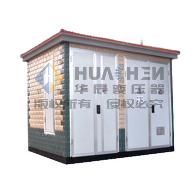
You must match the equipment design to the local utility infrastructure and your facility's reliability requirements. Selecting the wrong configuration delays grid interconnection and compromises site power stability.
Single-phase units primarily serve residential neighborhoods and light commercial service drops. You will recognize them as the smaller green boxes sitting on neighborhood lawns. They typically range from 15 kVA to 167 kVA. They step down power for standard 120/240V household panels.
Three-phase units handle heavy commercial, industrial, and institutional facilities. These sites require larger power loads and operate complex motor systems. Three-phase units range from 75 kVA up to 5,000 kVA. They provide secondary voltages like 208Y/120V or 480Y/277V, essential for running heavy HVAC equipment, elevators, and manufacturing machinery.
The primary feed configuration determines your site's vulnerability to utility outages. You must coordinate this choice with the local utility's underground grid design.
Radial Feed: This system features a single primary input. The power line terminates at the transformer. It offers a lower initial installation cost. However, if that single underground feed fails, the facility loses all power until the utility repairs the line.
Loop Feed: This system features two primary inputs. It connects to a continuous loop of power from the utility. The cabinet contains both a source connection and a feed-through connection. If one section of the utility line fails, technicians can isolate the fault using internal rotary switches and feed the unit from the other direction. This redundancy is vital for commercial and industrial facilities.
Radial Feed vs. Loop Feed Characteristics
Configuration Feature | Radial Feed Design | Loop Feed Design |
|---|---|---|
Primary Connections | Single input (terminates at unit) | Dual input (source and feed-through) |
Power Redundancy | None. Line failure causes total outage. | High. Can isolate faults and maintain power. |
Typical Application | End-of-line residential, isolated small commercial. | Industrial parks, hospitals, large commercial centers. |
Internal Bushings | Typically three high-voltage bushings. | Typically six high-voltage bushings. |
The connection method inside the primary compartment dictates operator safety and maintenance procedures.
Live-front construction represents a legacy design. When a technician opens the cabinet, the high-voltage terminals and connections are exposed. This design carries a higher risk of arc flash and electrocution. It requires specialized personal protective equipment (PPE) and strict clearance protocols during maintenance.
Dead-front construction is the modern safety standard. It utilizes insulated, shielded connectors known as loadbreak elbows. These elbows plug into the primary bushing wells, completely enclosing the high-voltage connections. There are no exposed live parts when the cabinet is open. This design drastically improves operator safety and reduces the risk of accidental contact.
When scaling up industrial operations, facility engineers must evaluate different infrastructure solutions. You will often compare a standalone Pad Mounted Transformer against a fully integrated Prefabricated Substation to determine the best fit for the site load.
Standard pad-mounted units handle a specific capacity range. They typically max out around 5,000 kVA. For most commercial buildings, retail centers, and mid-sized manufacturing plants, this capacity is more than sufficient. You can deploy multiple units across a large campus to distribute the load effectively.
A tipping point occurs when a facility's load profile exceeds these limits or requires complex internal distribution. Heavy industrial plants, data centers, and grid-scale solar farms necessitate a prefabricated substation. These substations integrate transformers, medium-voltage switchgear, low-voltage distribution panels, and protective relays into a single engineered enclosure. They handle much higher capacities and offer advanced load shedding and metering capabilities.
A single pad-mounted unit requires a relatively small physical footprint. You pour a standardized concrete pad, route the conduits, and crane the unit into place. The civil engineering requirements are straightforward and well-documented by local utilities.
A multi-component prefabricated substation demands extensive site preparation. The physical footprint is significantly larger. Civil engineers must design massive, reinforced concrete foundations. The site requires complex grounding grids, extensive trenching for multiple conduit banks, and often perimeter security fencing. While a substation offers superior capacity, the installation timeline and site footprint are exponentially larger.
Engineers and buyers need a structured framework to specify the correct equipment. Overlooking technical details leads to failed utility inspections and delayed facility commissioning.
Accurate sizing prevents equipment failure and wasted capital. You must calculate the required kVA based on three factors: continuous load, peak demand, and future expansion allowances. Electrical engineers perform a comprehensive load study based on the National Electrical Code (NEC) Article 220.
Undersizing causes the unit to overheat, degrading the internal insulation and drastically shortening its lifespan. Oversizing wastes upfront capital and increases no-load energy losses. A common practice involves sizing the unit so the facility's peak demand operates at roughly 75% to 80% of the transformer's maximum rating. This leaves headroom for future equipment additions.
Energy efficiency directly impacts long-term operational expenses. Equipment must comply with Department of Energy (DOE) efficiency standards. These regulations mandate specific maximum allowable energy losses for both no-load (core) and load (winding) conditions.
Buyers face a trade-off during procurement. Units built with ultra-efficient amorphous metal cores carry higher upfront costs. However, they significantly reduce continuous energy losses over a 30-year lifespan. You must evaluate the local utility rates to determine the payback period for high-efficiency models. Cheaper units often cost much more over their operational life due to wasted electricity.
Site-specific risks dictate containment and fluid choices. If you install the unit near a waterway, storm drain, or sensitive soil, a fluid leak poses a severe environmental hazard. In these cases, you must specify secondary containment pans or concrete moats around the pad.
Proximity to buildings dictates fire safety compliance. Mineral oil units require substantial physical separation from combustible walls, doors, and windows. If site constraints force the unit close to a building, you must specify less-flammable natural ester fluids. Upgrading the fluid type is often cheaper than building concrete blast walls or relocating the entire electrical service entrance.
Procuring the right equipment is only half the battle. Common failure points in site preparation and installation frequently delay commissioning. You must manage civil and electrical contractors tightly during this phase.
Proper grounding is non-negotiable for safety and operational stability. The unit features an equipment grounding mounting pad or plate. Electricians must bond this connection point to a driven ground rod array or a facility grounding ring using heavy-gauge bare copper wire and exothermic welds.
Improper bonding connections create severe hazards. If a fault occurs, poor grounding leads to step-and-touch potential hazards. This means the earth around the pad or the metal cabinet itself becomes energized, posing a lethal threat to anyone nearby. Furthermore, inadequate grounding prevents internal protective relays and fuses from clearing faults quickly, leading to extensive equipment damage.
Inspectors will fail an installation that violates clearance zones. The National Electrical Code (NEC) and National Electrical Safety Code (NESC) outline strict requirements. You must maintain specific working clearances so technicians can operate hot sticks and access internal components safely.
General rules require at least 10 feet of clear space in front of the cabinet doors. You must maintain 3 to 5 feet of clearance on the sides and back for airflow and visual inspection. You cannot plant dense shrubs or build fences within these zones. Additionally, you must adhere to utility-specific rules regarding distance from combustible building walls, fire escapes, and ventilation intakes.
The concrete pad serves as the foundation for the entire electrical service. It requires strict structural integrity. The pad must bear the immense weight of a fluid-filled steel tank without cracking or settling unevenly. Civil contractors must compact the soil properly and use steel rebar reinforcement.
Conduit stub-up placement requires absolute precision. The underground conduits carrying the primary and secondary cables must emerge from the concrete exactly where the cabinet's internal compartments are located. If the conduits are off by just a few inches, the cables will not align with the internal bushings. This error forces contractors to chip away the concrete pad or splice cables, causing massive delays and compromising the installation's integrity.
Concrete Pad Preparation Sequence
Excavate and compact the subgrade to prevent future settling.
Install the grounding ring and drive ground rods at the pad corners.
Route primary and secondary PVC conduits to the exact template dimensions.
Build the wooden forms and tie the steel rebar grid.
Pour 3000 PSI concrete and allow a minimum 7-day cure time before setting the equipment.
Ground-level distribution equipment remains the foundational choice for modern underground power grids. It offers a necessary balance of operator safety, site aesthetics, and reliable voltage step-down performance. Understanding the internal mechanics and site requirements ensures your facility receives stable, code-compliant power.
When finalizing your specifications, follow a strict decision matrix. Match the kVA rating and phase-type directly to your engineered load calculations. Select a radial or loop feed configuration based on the local utility's grid topology and your need for redundancy. Mandate dead-front construction to protect maintenance personnel. Choose dielectric fluids based on how close the unit sits to buildings or sensitive environmental areas.
Take immediate action to secure your project timeline:
Consult with your local utility provider to obtain their specific interconnection standards and approved equipment lists.
Finalize your load calculations with a licensed electrical engineer to prevent under-sizing.
Request detailed submittals and dimension drawings from manufacturers to guide your civil contractors during pad construction.
Schedule a pre-installation site walk with the utility inspector to verify clearance zones and conduit stub-up locations.
A: Primary voltages typically match utility distribution lines, commonly 12.47kV, 13.2kV, 24.94kV, or 34.5kV. The unit steps this down to secondary voltages usable by facilities. Common secondary voltages include 120/240V for residential, and 208Y/120V or 480Y/277V for commercial and industrial applications.
A: A well-maintained unit typically lasts 25 to 30 years. Lifespan depends heavily on operational conditions. Continuous overloading, poor dielectric fluid maintenance, severe weather exposure, and frequent short circuits will significantly reduce this expected operational life.
A: NEC and utility rules generally require 10 feet of clear space in front of the doors for safe hot-stick operation. You must maintain 3 to 5 feet of clearance on the sides and back. Clearances from buildings vary based on the dielectric fluid used and wall combustibility.
A: Ground-level units are necessary for underground distribution systems. They handle much higher kVA capacities than pole-mounted units. They eliminate vulnerability to weather-related line damage, such as falling trees or ice storms, and meet the strict aesthetic requirements of modern developments.
A: A radial feed unit connects to a single power source; if that line fails, the facility loses power. A loop feed unit connects to two power sources within a continuous utility loop, providing redundancy. Technicians can isolate line faults and maintain power from the secondary source.


