Jiangsu Huachen Transformer Co.,Ltd.
- All
- Product Name
- Product Keyword
- Product Model
- Product Summary
- Product Description
- Multi Field Search

Views: 0 Author: Site Editor Publish Time: 2026-08-02 Origin: Site


Understanding exactly what is a pad mounted transformer dictates how you design and build underground power grids. Ground-level distribution units replace overhead lines in areas with strict zoning laws, heavy canopy cover, or aesthetic restrictions. They sit on concrete foundations, stepping down high utility voltages to usable levels for buildings and industrial sites.
Engineers and contractors face strict constraints when specifying this equipment. You have to balance physical footprint, public safety, and environmental compliance. Tamper resistance matters because these units sit in public spaces. A poorly specified unit causes installation delays, failed inspections, and grid vulnerability.
This guide breaks down the technical evaluation framework for ground-level transformers. We cover internal configurations, dielectric fluid selection, and protection mechanisms. You will learn how to evaluate site requirements, pour proper pads, and terminate connections to ensure operational efficiency and regulatory compliance.
Core Function: A pad mounted transformer steps down high-voltage utility power to utilization voltages for residential, commercial, or industrial facilities, housed in a secure, tamper-resistant, grounded steel enclosure.
Design Variations: Selection depends heavily on phase requirements (single vs. three-phase), feed type (radial vs. loop), connection safety standards (dead-front vs. live-front), and regional manufacturing standards (ANSI/IEEE vs. IEC).
Alternative Solutions: For complex or high-capacity renewable projects, alternatives like a ZGS Combined Substation may offer superior integration and footprint efficiency compared to traditional pad-mounted units.
Procurement Focus: Decision-makers must evaluate kVA capacity, dielectric fluid type (mineral oil vs. ester fluids), integrated fusing, DOE efficiency standards, and site-specific environmental risks (e.g., coastal corrosion).
The steel cabinet acts as the primary physical barrier. Because these units sit at ground level in accessible areas, the enclosure must withstand weather, impacts, and vandalism. Manufacturers build these cabinets from heavy-gauge steel, typically mild steel for standard environments or 304L stainless steel for coastal and highly corrosive industrial sites. The metal gets a powder-coat finish to block rust and UV damage.
Compliance with IEEE C57.12.28 dictates the enclosure's integrity. The standard requires passing pry tests, hinge destruction tests, and lock manipulation trials. You will not find exposed hinges or standard padlocks on the exterior. The doors use recessed locking mechanisms secured by penta-head bolts. This specific bolt head requires a specialized utility wrench, keeping unauthorized people out of the high-voltage compartments.
The core-and-coil assembly sits submerged in dielectric fluid inside the main tank. This assembly executes the actual voltage step-down. It consists of primary high-voltage coils and secondary low-voltage coils wound around a silicon steel core.
Utility lines push high voltage into the primary side. You typically see primary voltages at 12.47 kV, 13.2 kV, or 34.5 kV. The magnetic field in the core induces a lower voltage in the secondary coils. The secondary side pushes out standard utilization voltages. Commercial sites usually take 480/277V or 208/120V. Residential neighborhoods run on 240/120V single-phase. The winding material—either copper or aluminum—affects the unit's overall weight, heat dissipation, and efficiency.
Distribution units carry internal safety devices to isolate faults. These mechanisms protect the upstream grid from local short circuits and protect the transformer from downstream overloads.
Bay-O-Net Expulsion Fuses: These sit in draw-out assemblies. They protect against secondary faults and overloads. A lineman can pull them externally using a hot stick to replace blown fuse links.
Current-Limiting Fuses: These dry-well fuses operate in series with the Bay-O-Net fuses. They clear massive high-level short circuits. They interrupt fault currents before internal arcing can rupture the tank.
Liquid Level Gauges: A simple visual dial on the tank exterior lets crews verify the dielectric fluid sits at the correct volume.
Thermometers: Dial-type thermometers track the top-oil temperature. High readings indicate overloading or blocked cooling radiators.
Pressure Relief Valves: If internal heat causes fluid to expand and build gas pressure, these mechanical valves pop open to vent the tank, preventing structural rupture.
Tap Changers: Externally operable, de-energized tap changers let technicians adjust the voltage ratio by a few percent. This fixes voltage drop issues at the end of long utility runs.
Phase configuration dictates the physical size and application of the unit. Single-phase transformers feed residential subdivisions and small retail buildings. They range from 10 kVA to 167 kVA. You see these compact green boxes sitting on utility easements in front yards.
Three-phase transformers handle heavy commercial and industrial loads. They power factories, hospitals, and data centers. These units range from 45 kVA up to 5000 kVA. The cabinets are massive because they house three separate coil windings.
Phase Configuration Specifications
Specification | Single-Phase Units | Three-Phase Units |
|---|---|---|
Typical kVA Range | 10 kVA - 167 kVA | 45 kVA - 5000+ kVA |
Primary Applications | Residential homes, small retail, street lighting | Industrial plants, hospitals, data centers, large commercial |
Secondary Voltages | 240/120V | 480/277V, 208/120V, 4160V |
Footprint | Compact (approx. 3x3 feet) | Large (up to 8x10 feet or more) |
The primary connection method determines grid redundancy. Radial feed systems use a single-source connection. The underground utility line ends at the transformer. This setup costs less because it requires fewer high-voltage bushings and less internal switching hardware. However, if that single utility line faults, the transformer goes dark until crews dig up and fix the cable.
Loop feed systems use a dual-source connection. The primary line enters the transformer, connects to the bus, and loops back out to feed the next transformer down the street. Loop feed units include internal V-blade or rotary switches. If a cable faults between two buildings, linemen can switch the internal feeds to isolate the bad cable while keeping both transformers energized from opposite directions.
Safety protocols dictate the primary connection style. Dead-front designs use insulated loadbreak elbows. The high-voltage cables terminate into thick rubber elbows that push onto epoxy bushings. When you open the primary cabinet door, you see no bare metal. Technicians use insulated fiberglass hot sticks to pull the elbows off the bushings. This is the standard for modern underground distribution.
Live-front connections use exposed terminal lugs and porcelain bushings. When you open the door, you look directly at bare, energized high-voltage metal. Live-front designs are rare in new construction but still appear in specific high-amperage industrial sites where standard 200A or 600A elbows cannot carry the load. Live-front maintenance requires strict clearance boundaries and specialized arc-flash suits.
Equipment specifications must match local utility standards. In North America, ANSI and IEEE standards govern transformer construction. IEEE C57.12.34 covers the electrical and mechanical requirements for three-phase pad-mounted units. Utilities build their concrete pad templates and conduit layouts based on these exact dimensions.
Other global markets use IEC standards. IEC-rated units have different testing protocols for temperature rise, short-circuit withstand, and basic impulse insulation levels (BIL). You cannot drop an IEC transformer onto an ANSI-designed grid without facing severe termination mismatches and failed electrical inspections.
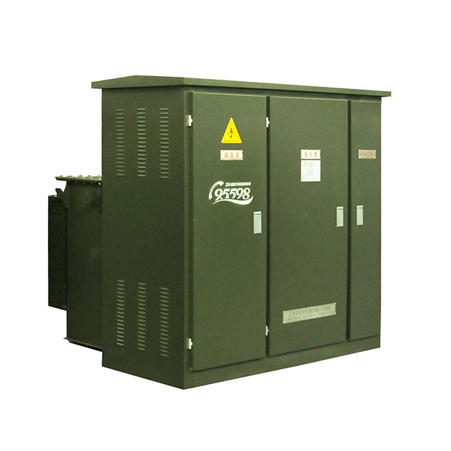
When site constraints tighten, contractors look at integrated equipment. A ZGS Combined Substation packages the transformer core, high-voltage load switches, and low-voltage distribution breakers into one steel housing.
A standard Pad Mounted Transformer only handles the voltage step-down. You have to run secondary cables from the transformer into a separate building to hit the main switchgear and distribution panels. The ZGS unit puts the switchgear inside the transformer housing.
Footprint drives the decision between these two setups. The ZGS unit requires one concrete pad. You trench your primary power in, and you trench your individual low-voltage branch circuits directly out of the substation to the loads. This eliminates the need for a massive indoor electrical room.
We specify ZGS units for solar farms, wind generation sites, and large EV charging depots. These sites lack large indoor electrical rooms to house secondary switchgear. Standard pad mounts work best for traditional commercial buildings where the main electrical room is already built into the architectural floor plan.
Equipment Integration Comparison
Feature | Traditional Pad Mount | ZGS Combined Substation |
|---|---|---|
Component Housing | Transformer core and coils only | Transformer, HV switch, LV breakers |
Site Footprint | Requires separate indoor/outdoor switchgear space | Highly compact; single outdoor foundation |
Trenching Requirements | Heavy secondary duct banks to main building | Direct branch circuit routing from the unit |
Ideal Applications | Warehouses, office buildings, residential | Solar farms, EV charging hubs, industrial yards |
Sizing the kVA capacity correctly prevents blown fuses and melted windings. You calculate the required kVA using the facility's peak demand load, not the average daily draw. Electrical engineers run load calculations based on NEC Article 220, factoring in lighting, HVAC, motors, and continuous loads.
You also have to account for harmonic distortion. Facilities with heavy variable frequency drive (VFD) usage, massive server farms, or DC fast chargers generate non-linear loads. These loads push harmonic currents back into the transformer, generating extreme heat in the core. If you have high harmonics, you must specify a K-factor rated transformer built with heavier windings to handle the thermal stress.
The fluid inside the tank insulates the energized coils and carries heat out to the external cooling fins. Mineral oil is the legacy standard. It cools effectively and costs less upfront.
Natural ester fluids, like FR3, dominate new commercial construction. Ester fluids have a much higher flash point (around 330°C compared to mineral oil's 165°C). This drastically reduces fire risk, allowing you to place the transformer closer to buildings. Ester fluids also absorb moisture out of the paper insulation wrapped around the coils, which physically extends the life of the transformer. If a tank ruptures, ester fluid is biodegradable, saving you from massive EPA soil remediation fines.
Dielectric Fluid Characteristics
Fluid Type | Flash Point | Environmental Impact | Primary Advantage |
|---|---|---|---|
Mineral Oil | ~165°C | Toxic to soil; requires heavy remediation | Lower initial capital expenditure |
Natural Ester (FR3) | ~330°C | Biodegradable; non-toxic | High fire safety; extends insulation life |
Silicone Fluid | ~340°C | Non-toxic but persists in environment | Extreme cold weather performance |
The Department of Energy (DOE) enforces strict efficiency mandates for distribution equipment. DOE 2016 standards require manufacturers to reduce internal electrical losses.
Transformers suffer from two types of losses. Core losses (no-load losses) happen 24/7 as long as the primary side is energized. The steel core consumes power just to maintain its magnetic field. Winding losses (load losses) fluctuate based on how much current the building draws. High-efficiency units use laser-cut, high-permeability silicon steel for the core and optimized copper windings to cut these losses down. You evaluate these loss metrics on the manufacturer's certified test report before accepting delivery.
You cannot drop a 10,000-pound piece of equipment on standard dirt. The concrete pad requires heavy rebar reinforcement and a deep compacted sub-base. The pad must sit perfectly level. If the pad tilts, the dielectric fluid inside the tank sloshes to one side, exposing the top of the coils to air and causing an immediate flashover.
The pad features block-out windows. These empty square holes in the concrete allow the underground PVC conduits to sweep up into the high-voltage and low-voltage compartments.
Grounding is critical. You must install a bare copper ground ring around the perimeter of the pad, buried 30 inches deep. You drive copper-clad ground rods at the corners and tie them to the ring using exothermic welds. The transformer tank grounds directly to this ring to eliminate step-and-touch voltage hazards for anyone walking near the unit.
The National Electrical Code (NEC) and local utility rulebooks dictate exactly where you can place the pad. You cannot hide the transformer behind dense bushes or shove it tight against a brick wall.
Linemen need physical space to work. You must leave a minimum of 10 feet of clear, flat space in front of the cabinet doors. This gives the operator room to stand back and use an 8-foot fiberglass hot stick to pull energized elbows. Side and rear clearances depend on the building's construction type and the fluid inside the tank.
Standard Clearance Requirements
Clearance Zone | Minimum Distance | Reasoning |
|---|---|---|
Front (Doors) | 10 Feet | Hot stick operation and safe escape path |
Sides and Rear | 3 to 8 Feet | Cooling airflow and exterior visual inspection |
Combustible Walls | 10 to 20 Feet | Fire prevention (distance drops if using ester fluid) |
Doors and Windows | 20 Feet | Prevents smoke ingress during a catastrophic failure |
Swapping out a dead transformer requires heavy logistics. You have to manage the facility outage. Hospitals and data centers require massive roll-up generators tied into the main switchgear before you can kill the utility feed.
Follow these steps for a safe replacement:
Verify the new transformer's footprint matches the existing concrete pad and conduit windows.
De-energize the primary utility feed and apply personal grounds to the cables.
Disconnect and pull back the primary elbows and secondary cables.
Rig the old transformer using a crane and four-point lifting slings attached to the factory lifting lugs.
Set the new unit, verify it is level, and terminate the high-voltage and low-voltage connections.
Perform insulation resistance (megger) testing before re-energizing the primary feed.
Transformers fail from environmental abuse and electrical stress. Enclosure corrosion destroys units in coastal areas. Salt fog eats through the powder coat, rusting the steel until water leaks into the high-voltage compartment.
Lightning strikes and utility switching surges destroy the internal coils. If the external surge arresters fail to clamp the voltage spike, the surge punches through the paper insulation, shorting the windings together. Overloading the unit beyond its nameplate kVA rating boils the dielectric fluid, degrades the paper insulation, and eventually causes a dead short.
You keep these units alive through aggressive testing. Do not wait for the lights to go out.
Dissolved Gas Analysis (DGA): Pull a fluid sample from the drain valve annually. A lab analyzes the oil for trace gases. High hydrogen indicates partial discharge. High ethylene indicates severe overheating. DGA tells you the transformer is dying months before it actually fails.
Infrared Thermography: Scan the primary elbows and secondary spades with a thermal camera while the unit is under heavy load. Loose mechanical lugs show up as bright white hotspots. You can schedule an outage to torque the lugs before they melt off the busbar.
Visual Inspections: Walk the pad quarterly. Check the fluid level gauge. Look for oil weeping around the bushing gaskets or radiator fins. Verify the padlock and penta-head bolts are secure.
Audit your facility's peak demand load and harmonic profile with a licensed electrical engineer to determine the exact kVA and K-factor requirements.
Submit your site plans to the local utility provider to confirm concrete pad dimensions, conduit window placement, and mandatory clearance boundaries.
Specify natural ester fluids for any installation located near combustible building walls or environmentally sensitive areas.
Request certified test reports from the manufacturer to verify the unit meets DOE 2016 efficiency standards for core and winding losses.
A: It steps down high-voltage utility power to safe utilization voltages for underground distribution systems. Contractors install these units on concrete foundations to supply electricity to residential homes, commercial buildings, and industrial sites where overhead power lines are restricted or impractical.
A: Pole-mounted units bolt to wooden or concrete utility poles and connect directly to overhead power lines. Pad-mounted units sit at ground level on engineered concrete foundations and connect exclusively to underground high-voltage cables routed through PVC conduits.
A: They use heavy-gauge, tamper-resistant steel enclosures secured with penta-head bolts. Internally, they rely on Bay-O-Net expulsion fuses to clear overloads and backup dry-well current-limiting fuses to interrupt massive short circuits before the tank ruptures.
A: No, they are engineered for outdoor installation. The dielectric fluid presents a fire hazard, and the units require open-air circulation to cool the external radiator fins. Indoor installations require dry-type transformers or specialized fire-rated concrete vaults.
A: You must leave at least 10 feet of completely clear space in front of the cabinet doors so linemen can safely use fiberglass hot sticks. Side and rear clearances require 3 to 8 feet of unobstructed space to ensure proper cooling airflow.
A: A dead-front connection means all high-voltage components are fully insulated. The cables terminate into thick rubber loadbreak elbows. When you open the cabinet, no energized bare metal is exposed, drastically reducing the risk of accidental electrocution or arc flash.