Jiangsu Huachen Transformer Co.,Ltd.
- All
- Product Name
- Product Keyword
- Product Model
- Product Summary
- Product Description
- Multi Field Search

Views: 0 Author: Site Editor Publish Time: 2026-08-21 Origin: Site


Medium-voltage electrical installations demand absolute precision. Improper transformer installation leads to catastrophic equipment failure, severe safety hazards, and costly grid downtime. Procuring high-value electrical assets solves only part of the infrastructure equation. Achieving safe, compliant, and efficient energization requires mastering site preparation, rigorous compliance standards, underground system integration, and precise termination requirements.
Field engineers and electrical contractors face strict tolerances when placing and terminating heavy apparatus. A minor deviation in pad leveling or a compromised ground connection can result in arc flashes or premature insulation breakdown. We provide a structured, standard-compliant framework detailing the technical phases of how to install a pad mount transformer, from initial site evaluation and equipment handling to final pre-energization testing.
Site Readiness is Non-Negotiable: Proper concrete pad curing, structural leveling, and adherence to NESC clearance codes are prerequisites for a safe, weather-exposed installation.
Rigorous Pre-Installation Inspection: Identifying shipping damage, compromised seals, or dielectric fluid leaks before positioning prevents energizing faulty equipment.
Precision in Terminations and Grounding: Strict adherence to torque specifications and IEEE grounding standards mitigates the highest-probability risks of arc flashes and premature equipment failure.
Mandatory Pre-Energization Testing: Insulation resistance (Megger), Transformer Turns Ratio (TTR), and fluid level verification must be documented prior to applying primary voltage.
A successful installation begins long before the equipment arrives on site. The concrete mounting pad serves as the foundation for operational stability. Engineers must verify the pad's weight-bearing capacity against the transformer's maximum operating weight, including fluid. You need a minimum of 3000 PSI concrete reinforced with a steel rebar grid. Leveling tolerances are strict. An uneven pad causes cabinet distortion, misaligned doors, and uneven dielectric fluid distribution across internal coils. Conduit stub-ups must align perfectly with the high-voltage and low-voltage compartment openings to prevent severe cable bending radiuses.
Environmental and spatial evaluations dictate physical placement. Installers must enforce National Electrical Safety Code (NESC) and Occupational Safety and Health Administration (OSHA) clearance requirements. Standard codes mandate specific distances from buildings, doors, fire escapes, and combustible materials to mitigate fire risks. Typically, this requires a minimum of 10 feet of clear workspace in front of the cabinet doors for hot-stick operation and 2 to 3 feet of clearance on the sides and rear.
Soil resistivity testing directly impacts the grounding grid design. Field technicians use the Wenner four-pin method to measure soil resistance, determining the depth and spacing of driven ground rods. High-resistivity soil may require soil enhancement materials or an expanded ground ring to achieve the required low-resistance path to earth.
Follow these site preparation steps before scheduling equipment delivery:
Excavate the sub-base and compact a 6-inch layer of crushed gravel for drainage.
Install and secure all PVC conduit sweeps, ensuring they extend exactly 2 to 3 inches above the final concrete grade.
Drive the primary copper-clad ground rods and route the grounding tails into the designated pad opening.
Pour the concrete and allow a minimum 7-day curing period before placing heavy apparatus.
Selecting the right apparatus requires a clear decision framework evaluating footprint, compartmental design, and integration requirements. Installers must differentiate between single-phase units and three-phase compartmental type transformers. Single-phase units typically serve residential applications, featuring smaller footprints and simpler loop-feed or radial-feed terminations. Three-phase units serve commercial and industrial underground systems, requiring larger pads, complex phase alignment, and heavier lifting equipment.
Project scope determines whether to deploy a standard Pad Mounted Transformer or a fully integrated ZGS Combined Substation. Standard transformers provide basic step-down functionality. Combined substations integrate high-voltage switchgear, the transformer core, and low-voltage distribution into a single engineered enclosure. These units are highly effective for renewable energy sites or industrial parks.
Evaluate the trade-offs carefully. Standard units offer straightforward installation but may require separate downstream switchgear. Combined substations optimize the overall site footprint and reduce external cabling but introduce higher installation complexity and require specialized rigging due to their asymmetrical weight distribution.
Equipment Application and Footprint Comparison
Equipment Type | Primary Application | Installation Complexity | Footprint Efficiency |
|---|---|---|---|
Single-Phase Pad Mount | Residential subdivisions, light commercial | Low - Standard rigging and simple terminations | High - Compact design fits tight easements |
Three-Phase Pad Mount | Commercial buildings, industrial facilities | Medium - Requires heavy cranes and phase alignment | Moderate - Requires larger concrete pads |
ZGS Combined Substation | Solar farms, wind parks, heavy industrial | High - Asymmetrical lifting, integrated switchgear | Maximum - Eliminates need for separate switchgear pads |
Replacing an existing unit introduces unique logistical hurdles. Specific protocols govern the safe decommissioning and removal of damaged or obsolete transformers. Technicians must execute strict Lock-Out/Tag-Out (LOTO) procedures, verify the absence of voltage using a high-voltage proximity tester, and safely drain or contain any leaking dielectric fluid before lifting the old unit.
Complex change-outs often require maintaining power continuity. This involves paralleling temporary transformers. Crews must verify phasing, voltage ratios, and impedance matches before connecting the temporary unit to the live grid. Once the temporary feed is stable, the primary unit can be disconnected.
Never assume the existing infrastructure is adequate for the new equipment. Inspect the existing concrete pad for cracking, subsidence, or rebar exposure. Verify the integrity of the existing grounding ring. Upgrading the grounding system or pouring a new pad is often necessary to meet current safety standards before placing the new unit.
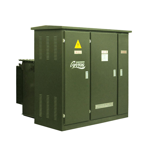
Equipment inspection begins the moment the delivery truck arrives. Do not sign the bill of lading until a thorough visual assessment is complete. Check all impact indicators attached to the packaging. Inspect the outer tank for structural deformation, deep scratches that compromise the powder coating, and verify the integrity of all tamper-proof hardware.
Once the exterior is cleared, open the cabinet doors. Inspect the high-voltage and low-voltage compartments. Look for any signs of moisture ingress during transit. Check the base of the bushings, the pressure/vacuum gauges, and the drain valves for any trace of dielectric fluid leaks. A leaking transformer must not be positioned or energized.
Verify the nitrogen blanket pressure if the unit shipped with positive pressure. A zero reading on the pressure gauge indicates a compromised tank seal. You must investigate and resolve this before accepting the equipment.
Lifting heavy electrical apparatus presents severe physical risks. Always verify the crane or forklift load capacities against the exact nameplate weight of the transformer. Never estimate the weight. The lifting equipment must exceed the total weight by a safe margin to account for dynamic loads during the swing.
Utilize only the designated lifting lugs welded to the transformer tank. Employ proper spreader bars and slings to maintain the correct center of gravity. Failure to balance the load can cause the unit to tilt, potentially shifting the internal core and coil assembly, which ruins the transformer before it ever touches the pad.
Execute the lifting and positioning sequence as follows:
Attach certified rigging hardware to all four lifting lugs using shackles.
Tension the slings slowly to verify the center of gravity and ensure the unit lifts perfectly level.
Hoist the unit clear of the transport vehicle and swing it smoothly toward the concrete pad.
Position spotters at opposite corners of the pad to guide the unit over the conduit stub-ups.
Lower the unit onto the concrete pad with extreme caution, ensuring no conduits are crushed.
Mechanical fastening prevents equipment shifting during seismic events, high winds, or accidental impacts. Align the transformer base perfectly with the pre-cast pad inserts or drilled anchor points. Secure the unit using heavy-duty, corrosion-resistant anchoring hardware, such as stainless steel wedge anchors or epoxy-set threaded rods.
Apply a weather-tight mastic seal or specialized grout between the transformer base and the concrete pad. This seal serves multiple purposes. It prevents rodent and insect ingress into the high-voltage compartment, stops water pooling under the base, and maintains the overall compartmental security required by utility codes.
Grounding is the single most critical safety and operational step in the installation process. A compromised ground path guarantees equipment failure and lethal safety hazards during a fault. Connect the primary transformer tank ground pad directly to the site's grounding grid using appropriately sized bare copper wire, typically 4/0 AWG, and exothermic welds or heavy-duty mechanical lugs.
Route the concentric neutrals from the primary cables and the system grounds to the designated ground bus within the cabinet. Strict adherence to IEEE standards for grounding medium-voltage equipment is mandatory. Ensure all connections are wire-brushed, coated with antioxidant compound, and torqued to specification.
Drive supplemental ground rods inside the pad opening if the utility requires a triad configuration. Bond these rods together and connect them to the main tank ground. Test the completed ground ring with a clamp-on earth resistance tester to ensure the impedance is below 5 ohms.
Primary connections require absolute cleanliness and precision. Evaluate the termination types specified for the project: loadbreak elbows, designed to be connected or disconnected under load using a hot stick, versus deadbreak elbows, which are bolted connections requiring de-energization.
Prepare the medium-voltage underground cables using specialized stripping tools to prevent scoring the underlying XLPE or EPR insulation. Roll back the concentric neutral wires and secure them. Use a chamfer tool on the insulation edge to allow smooth insertion into the elbow housing. Apply the manufacturer-approved dielectric silicone grease to the bushing interfaces and the cable insulation. Seat the elbows firmly onto the primary bushings, ensuring the locking rings engage completely.
Implement proper strain relief for all incoming cables. High-voltage cables are heavy. If left unsupported, their weight pulls down on the primary bushings, causing mechanical stress, micro-cracks in the epoxy, and eventual dielectric fluid leaks. Install cable support brackets inside the high-voltage compartment.
Secondary terminations handle massive current loads, making them highly susceptible to thermal expansion issues. Route the low-voltage cables neatly into the secondary compartment, maintaining safe air clearances between phases and ground. Terminate the cables to the secondary spades using NEMA-drilled aluminum or copper lugs.
Wire-brush the spade surfaces and apply a liberal coat of joint compound, like Noalox, to prevent oxidation. Fasten the lugs using the correct torque values specified in the manufacturer's manual. You must utilize Belleville washers in the hardware stack. These conical spring washers flatten under proper torque and expand or contract with the thermal cycling of the transformer, ensuring the connection remains tight under heavy load.
Assemble the hardware stack in this exact order: bolt, flat washer, terminal lug, transformer spade, flat washer, Belleville washer, and nut. The crown of the Belleville washer must face the nut.
Standard Torque Specifications for Secondary Terminations
Hardware Size | Material Type | Recommended Torque (ft-lbs) |
|---|---|---|
1/2 inch | Aluminum to Aluminum | 40 - 50 |
1/2 inch | Copper to Copper | 40 - 50 |
5/8 inch | Aluminum or Copper | 55 - 70 |
3/4 inch | Aluminum or Copper | 100 - 120 |
Never apply primary voltage without documenting baseline electrical diagnostics. These tests confirm the equipment survived transit and installation without internal damage. Perform Insulation Resistance (Megger) testing, typically at 1000V or 2500V, to verify the integrity of the winding insulation against the core and ground. Low resistance readings indicate moisture ingress or insulation damage.
Execute a Transformer Turns Ratio (TTR) test across all tap settings. This confirms the tap changer is functioning correctly and verifies the health of the internal coils. The measured ratio must not deviate more than 0.5% from the calculated nameplate ratio. Conduct winding resistance testing to establish a baseline for future preventive maintenance comparisons.
Verify the dielectric fluid levels using the site glass or dipstick. Check the internal tank pressure using the pressure/vacuum gauge. A slight positive or negative pressure indicates the tank seal is intact. If the gauge reads exactly zero, the seal may be compromised, requiring further leak investigation.
Clean all bushings and stand-off insulators thoroughly. Use approved lint-free cloths and non-residue evaporative solvents. Dust, dirt, and moisture accumulated during construction create conductive paths. Do not energize without thoroughly cleaning the bushings. Failure to do so results in electrical tracking and explosive flashovers.
Manually verify the operation of the pressure relief device (PRD). Check the tap changer mechanism to ensure it is locked securely in the correct operational position. Energizing a transformer with an unsecured tap changer causes immediate catastrophic failure.
Transformer Pre-Energization Verification Checklist
Component / System | Verification Action | Acceptance Criteria |
|---|---|---|
Grounding Grid | Measure earth resistance and verify lug torque. | Resistance < 5 ohms; lugs torqued to spec. |
Dielectric Fluid | Check fluid level gauge and pressure/vacuum gauge. | Fluid at 25°C mark; non-zero pressure reading. |
Primary Bushings | Clean surfaces and inspect elbow seating. | Zero dust/moisture; locking rings fully engaged. |
Secondary Spades | Verify hardware stack and torque values. | Belleville washers flat; antioxidant applied. |
Internal Coils | Perform TTR and Megger testing. | < 0.5% TTR deviation; high insulation resistance. |
The most common point of failure in transformer installations is improper torqueing of secondary connections. Under-torqued bolts create high-resistance connections. As current flows, these connections overheat, melting the insulation and eventually causing a phase-to-phase fault. Over-torqued bolts strip threads or crack the secondary spades. Always use calibrated torque wrenches.
Moisture ingress during the construction phase is another severe risk. Open cabinets exposed to rain or high humidity absorb moisture into the dielectric fluid and paper insulation. Mitigate this by keeping doors closed whenever possible, using temporary weather shelters during cable termination, and placing industrial desiccant packs inside the cabinet until final energization.
Regulatory compliance dictates site safety. Installers must navigate NFPA 70E standards regarding arc flash safety, ensuring proper labeling is applied to the cabinet exterior based on fault current calculations. NESC guidelines dictate the physical security of the installation, requiring penta-head bolts and padlocks to prevent unauthorized public access.
Before contacting the utility for power delivery, conduct a final site walk-through. Verify all tools are removed from the cabinet, all grounds are secure, and the concrete pad area is clear of debris. Utility inspectors will reject the installation if clearance codes are violated or if testing documentation is incomplete.
Successful transformer installation relies entirely on strict adherence to mechanical tolerances, electrical testing protocols, and safety standards. Cutting corners on pad preparation, cable termination, or grounding directly threatens grid stability and human life. Engineering precision during the physical placement phase dictates the long-term reliability of the electrical asset.
You know an installation is ready for energization when all mechanical anchors are secure, primary and secondary connections are torqued and marked, grounding resistance meets utility specifications, and all Megger and TTR tests pass without deviation. Only after the utility inspector signs off on these metrics should primary voltage be applied.
Execute these next steps to finalize the installation and ensure long-term reliability:
Establish a baseline maintenance schedule immediately post-energization.
Schedule the first dissolved gas analysis (DGA) sample within six months to detect early internal fault conditions.
Implement annual infrared thermography inspections on all secondary spades and primary elbows to identify high-resistance thermal anomalies.
Verify all utility sign-off documentation is archived with the facility's electrical safety program.
A: NESC standards require a minimum of 10 feet of clear workspace in front of the cabinet doors to allow technicians to use hot sticks safely. The sides and rear generally require 2 to 3 feet of clearance, depending on the proximity to combustible materials, building overhangs, and fire escapes.
A: Yes, grounding is absolutely mandatory. The transformer tank and internal ground bus must connect to a dedicated ground ring or driven ground rods using heavy-gauge bare copper. This ensures immediate fault clearing, prevents the tank from becoming energized, and protects personnel from lethal step-and-touch potentials.
A: Mandatory pre-energization tests include Insulation Resistance (Megger) testing to verify winding integrity, Transformer Turns Ratio (TTR) testing to confirm coil health and tap settings, and winding resistance tests. Technicians must also verify dielectric fluid levels, check internal tank pressure, and visually inspect all terminations.
A: No. Installing on an uneven pad causes severe structural and operational issues. The heavy weight distorts the metal cabinet, causing doors to bind and compromising the weather-tight seal. An uneven tilt causes improper distribution of dielectric fluid, exposing internal coils and causing catastrophic failure.
A: A standard pad mount transformer performs voltage step-down functions and requires separate upstream or downstream switchgear. A ZGS Combined Substation integrates the high-voltage load break switches, fuses, transformer core, and low-voltage distribution breakers into a single, compact enclosure, optimizing space for complex industrial sites.
A: Bushings must be wiped down using a clean, lint-free cloth and an approved non-residue evaporative solvent. This removes dust, dirt, and moisture accumulated during transit and installation. Energizing dirty bushings creates conductive paths that lead to electrical tracking and explosive flashovers.